Modeling Communication Topology
Back to Intro
So far, we have only considered failure of devices but now how they are connected. We only had

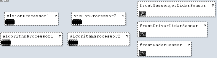
Now, we are adding a communication topology:
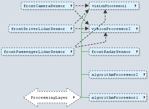
The camera and both lidars are connected directly to both vision processors using discrete connectors. The radar and all processors are connected via Ethernet.
In our model, the functional analysis remains the same but we add a communication topology to the hardware architecture and extend the deployment of functional connectors to hardware connectors.
AutoPilot : System
AP_HA : HardwareArchitecture
AP_CT : CommTopology
AP_Dpl : Deployment
// nodes
[ AP_FAA.dynamicObjectDetection.deployedTo in AP_DN.algorithmProcessor1, AP_DN.algorithmProcessor2 ]
// connectors
[ AP_FAA.frontDriverLidarVal.deployedTo.dref in AP_CT.frontDriverLidarData1, AP_CT.frontDriverLidarData2 ]

Back to Modeling FAA Re-configurations
Back to Intro
abstract FAA : FunctionalAnalysis
dynamicObjectDetection : AnalysisFunction ?
// Function Connectors
[ degradation = if frontRadarVal && pointCloudCusterVal then 1 else if frontCameraVal && pointCloudCusterVal then 2 else 3 ]
The reference model remains unchanged.
abstract System
abstract FeatureModel
abstract Architecture
abstract FunctionalAnalysis
abstract HardwareArchitecture
abstract DeviceNodeClassification
abstract CommTopology
abstract PowerTopology
abstract Deployment
abstract Feature
abstract FunctionalAnalysisComponent
// level 4 implies that the function is not available
xor implementation
hardware
software
enum DeviceNodeType = SmartDeviceNode | EEDeviceNode | PowerDeviceNode
abstract HardwareConnector
// Automotive Concepts