Modeling hardware failures
Back to Intro
While the fixed example captures the structure of the auto pilot system there are no interesting properties we can investigate. For example, imagine we wanted to observe whether the system would still be functional if one of the vision and algorithm processors failed. This would be interesting for two reasons:
- We can test the tolerance of the system to certain hardware faults.
- We can synthesize the various designs due to the reconfiguration of the system in response to hardware faults.
For the purposes of this example we consider a hardware fault only to be the failure of a device node (i.e. it is as if the device node has been removed from the system).
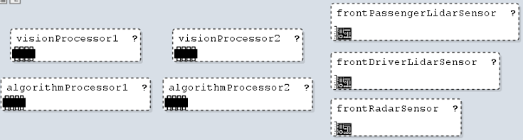
To enable this analysis, we must first add variability to the device
nodes. We do this by marking each device node optional (with
multiplicity 0..1 denoted by ?).

Reference model
First our reference model, in which we now have the concepts of deployment and device node:
Architecture of the autopilot system
Then, below the functional analysis architecture, we add the hardware architecture with optional devices, as well as, the deployment of the functional to the hardware layer.
Next we have to update the deployment constraints in which we want to say that the analysis functions can be deployed to either processing unit. This allows us to model a failure of a device node and as long as there exists another device node to which the function can be deployed to.
Exploration scenarios
Then using this model we can model a couple of different scenarios.
The fist scenario is to remove one of the vision and algorithm
processors. The architecture can still be synthesized despite and
unavailability of these two nodes. It means that our system is still
functional after the failure of visionProcessor1 and
algorithmProcessor1.
However, if we were to model the failure of the front radar as follows:
We would find that we get UNSAT from the solver. This translates to saying that if we lose the front radar sensor, the system is no longer functional (i.e., the system has failed).

Back to Intro