Telematics Product Line Architecture
Vehicle telematics systems integrate multiple telecommunication and information processing functions in an automobile, such as navigation, driving assistance, emergency and warning systems, hands-free phone, and entertainment functions, and present them to the driver and passengers via multimedia displays.
Summary of concepts
Detailed model
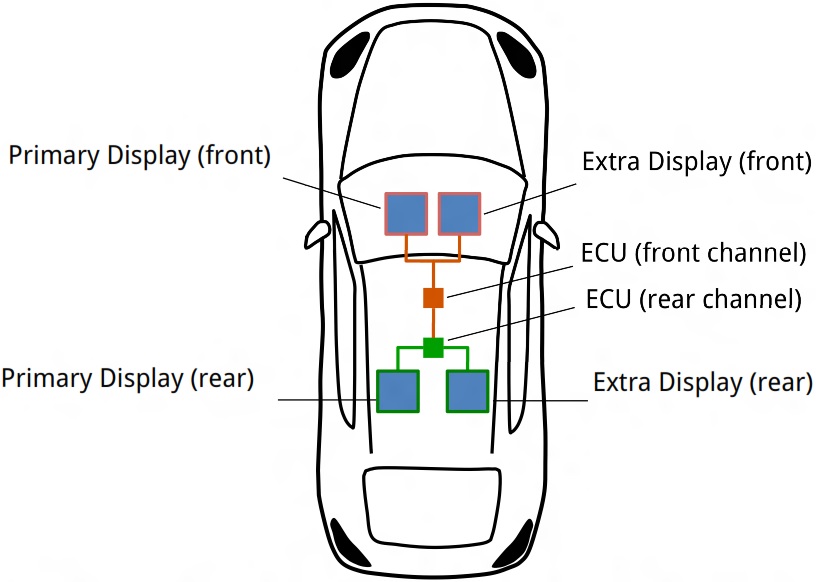
A concrete telematics system can support either a single or two channels; two channels afford independent programming for the driver and the passengers. The choice is represented as the xor-group channel. By default, each channel has one associated display; however, we can add one extra display per channel, as indicated by the optional feature extraDisplay. Finally, we can choose large or small displays (displaySize).
There are two types of components: ECUs (electronic control units) and displays. Each display has exactly one ECU as its server. All components have a version. Components themselves may have options, like the display size or cache. We can also specify the cache size and decide whether it is fixed or can be updated dynamically. Thus, the solution space model consists of a class model of component types and a feature model of component options.

and the two types of components:
Reusable options are defined as follows:
The architectural meta-model is very generic: the meta-model describes infinitely many different products, each corresponding to its particular instance. We would like to specialize and extend the meta-model to create a particular template. A template makes most of the architectural structure fixed, but leaves some points of variability.
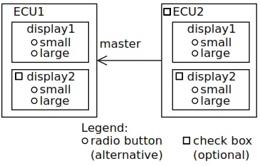
a concrete product must have at least one ECU and thus we create ECU1 to represent the mandatory instance. Then, optional instances are represented using classes with cardinality 0..1. Our product line can optionally have another ECU, represented by ECU2. Similarly, each ECU has either one display or two displays, but none of the displays has cache. Besides, we need to constrain the server reference in each display in plaECU, so that it points to its associated ECU - this constraint is nested under display. The reference parent points to the current instance of plaECU, which is either ECU1 or ECU2.Also, ECU2 extends the base type with master,pointing to ECU1 as the main control unit.

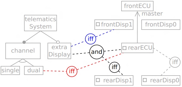
Having defined the architectural template, we are ready to expose the remaining variability points as a product-line feature model. A set of constraints coupling its features to the variability points of the template. Note that the template allowed the number of displays (ECU1.display and ECU2.display) and the size of every display to vary independently; however, we further restrict the variability in the feature model, requiring either all present ECUs to have two displays or all to have no extra display and either all present displays to be small or all to be large. Also note that we opted to explain the meaning of each feature in terms of the model elements to be selected rather than defining the presence condition of each element in terms of the features. Both approaches are available in Clafer, however. Constraints allow us restricting a model to a single instance. The following code block shows a top-level constraint specifying a single product, with two ECUs, two large displays per ECU, and all components in version 1.

