Directed Graph Reachability in Presence of Variability
Metamodeling a directed graph
We can model a directed graph with non-zero weighted edges as follows:
That is, every node can be connected to zero or more other nodes and
multiple edges in the same direction are allowed between any two nodes.
To only allow at most one edge in the same direction between any two
nodes, one would use a set-valued reference:
abstract Edge -> Node *.
We compute total weight of all edges present in a graph as follows:
Modeling a concrete graph
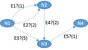
Then, we can specify a concrete graph in which every edge is optional shown below. The optionality of the edges is indicated using question marks, and the weights are shown in parentheses.
We model the example graph in Clafer directly as follows. Note, that
we are refining the original reference clafer
Edge:
->>(bag) into->(set),*into?, and- type
Nodeinto the specific nodes (N1,N2, etc.)
Expressing reachability constraint
Now, we would like to express a constraint that the node
N4 must be reachable from N1. That is not
currently possible in Clafer 0.4.1; however, as of 0.4.1 we can use
Alloy escapes to write the constraint directly in Alloy. Markers
[alloy| and |] indicates the beginning and the
end of embedded Alloy code.
[alloy|
fact {
    c0_N4 in c0_N1.^(r_c0_Edge.c0_Edge_ref)
}
|]
The expression r_c0_Edge.c0_Edge_ref computes a relation
Node->Node, so that we can compute a transitive closure
of that relation and thus express the reachability constraint.
When writing Alloy code in the escapes, we have to use names from the
Alloy output generated by Clafer compiler. A simple rule is that
whenever a name of a clafer is unique, it will always be prefixed with
c0_ in the Alloy output. Non-unique clafer names have
prefixes c0_, c1_, …, assigned in the order of
the appearance of the clafers in the model.
For reference, here’s the relevant Alloy output generated for clafers
Node and Edge:
abstract sig c0_Node
{ r_c0_Edge : set c0_Edge }
The field r_c0_Edge is a relation
c0_Node->c0_Edge.
abstract sig c0_Edge
{ c0_Edge_ref : one c0_Node }
{ one @r_c0_Edge.this }
The field c0_Edge_ref is a relation
c0_Edge->c0_Node. Thus, the composition
r_c0_Edge.c0_Edge_ref is a relation
Node->Node.
In ClaferIDE, you can see the Alloy output in the
Compiled Formats window by selecting
Alloy Model:

Playing with the model
Use ClaferIDE with the Alloy-based backend to see all graphs in which
the node N4 is reachable. The Choco-based backend does not
yet support nested abstract clafers but one can already escape into
chocosolver’s JavaScript using the [choco| …
|] escape.
Tip: in IDE, you can keep the ClaferIG session running but you must click on
Compilebutton after each change to the model. ClaferIG will then reload the session and keep all settings, such as, scopes and bitwidth.
Can you make
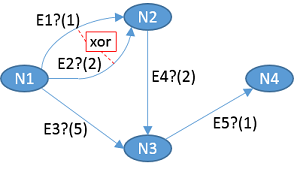
N1prohibited (that is give it cardinality0) and get an instance? Why?Make the edges
E1andE2mutually exclusive. You can use thexoroperator. We would like to obtain a graph which can be visualized as follows:
- Can you make
N1optional and get an instance withoutN1? Why?
Make the node
N2prohibited and see what happens. Is that what you expected? Why aren’t there more instances?Make the node
N2optional (that is give it cardinality?) and see what happens. Is that what you expected?- Then add a constraint
[no N2].
- Then add a constraint
Make the edge
E2point to eitherN2orN3. We would like to obtain a graph which can be visualized as follows:
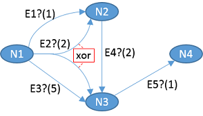
Note that this case is different from point 2, where we have two different edges which are exclusive. Here, we have a single edge which can have different targets.
See answers to these questions at the end of page.
Model summary
Finally, here’s a summary of our model. Double click on the graph to show/hide references.
Our example graph is actually visible in the graphical rendering of our model. Why? Only because we used reference refinement and we specified the targets of edges as types of the references. That made this information available statically. Had we used constraints to specify the targets of the edges, this information could only be obtained by constraint solving and it would be different for every instance. Thus, using reference refinement makes more structure statically visible compared to using constraints from which such structure is hard to recover.
Answers to the questions
No. The reachability constraint requires
N4to be in a set of nodes reachable fromN1. IfN1is empty, so is the set of reachable nodes, and soN4cannot be in an empty set.The constraint can be written as
[E1 xor E2].
- No, if the constraint is nested under
N1. In this case, ignoring the reachability constraint, thexormeans that exactly one ofE1andE2must be present. For that to be true,N1must always be present because the edges are nested under nodes andE1andE2cannot exist without their parent nodeN1. To mitigate that, we could also nest the constraint underN1, so that the constraint only must hold when an instance ofN1is present:
N1 : Node
    [E1 xor E2]
...
Because
N2is not present, there cannot be any edges incoming to or outgoing fromN2, which leaves only one possible path viaE3andE5.Yes. Graphs both with or without
N2are possible. Adding the constraintno N2is equivalent to makingN2prohibited as in point 3.The idea that an edge points to either
N2orN3can be formalized by introducing an derivedsumnodeN2++N3which represents the union of the two nodes. Such a derived node can then be used as a target ofE2.
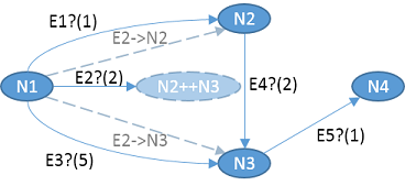
Also, observe that we now have two derived projections of
E2 called E2->N2 and
E2->N3, which illustrates the possible concrete edges in
a resulting graph.
Concretely, specify the target type of the edge E2 as
N2 ++ N3, that is, E2 : Edge -> N2 ++ N3 ?.
Observe that the edge is still optional, meaning there will be at most
one instance of E2 in the model. The type specifies the set
of valid values from which at most one can be taken due to the
cardinality. That is significantly different then specifying a
constraint
E2 -> Node 2
[ E2 = N2 ++ N3 ]
Constraints are expressed over instances and this constraint
specifies there will be two instances of the edge E2, such
that E2$1 = N2 and E2$2 = N3.